4-Channel Temperature Monitor/Logger
This project was born of necessity. I needed to monitor the temperature rise of various components and didn't want to spend a lot of money on an expensive commercial solution. I require a minimum of two channels to measure the delta between ambient and some component. Ideally a system would support more than two channels in order to measure additional temperature points. I looked at several solutions including thermocouples, thermistors, and diode-based sensors using both I2C and analog signaling but finally settled on the Maxim DS18B20 1-wire digital thermometer (spec). It is accurate enough for my application (+/- 0.5 C) but more importantly provides a very simple interface enabling a system utilizing very thin wires for the temperature probes (old earphone cables). I briefly considered writing some PIC code but quickly found a set of Arduino libraries that made the processor decision easy.
Monitor Specs
Hardware
This entire project was made possible by the use of open source libraries. The amount of coding these four libraries saved me is simply amazing.
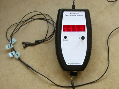
- Enclosure: Pactec HRP-2AA (battery compartment gutted)
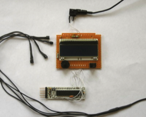
- Processor: Arduino on a Modern Device RBBB board (spec)
- Display: Electronic Assembly DOG-M 2x16 character LCD in SPI mode (including backlight module)
- Sensors: 4 x DS18B20 1-wire digital thermometer attached to a 2-wire earphone cable
- Interface: 9600 baud TTL-serial for FTDI FT232R cable (programming and USB-serial interface) or BlueSMiRF Radio (Bluetooth Serial)
- LCD Display: Displays 4 temperatures + Delta values from lowest temperature
- Units: C or F
- Serial Interface: Logs timestamp and 4 temperature values approximately every 1.5 seconds
Open Libraries To The Rescue
This entire project was made possible by the use of open source libraries. The amount of coding these four libraries saved me is simply amazing.
- Jan Krutisch's LCDdogmSPI Arduino library
- Jim Studt's OneWire Arduino library (version 2.0)
- Miles Burton's DallasTemperature Arduino library (version 3.7.0)
- Roger Meier's DataPlotClasses Real Studio library (version 1.2.1 with some mods)
Very simple hardware. I didn't even make up a schematic until I went to document the project.
The RBBB programming connector is also the TTL serial port. This port can connect to the FTDI cable, a bluetooth radio and +5 volt external power supply or even a level-shifter in order to connect the monitor to a RS232 port.
The DS18B20 parts require only two parallel wires enabling the (re)use of a very thin and flexible earphone cable. All four sensors are wired together and the connections protected with heat-shrink tubing.
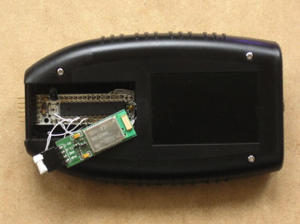
A very old BlueSMiRF bluetooth modem was pressed into service to enable wireless connection with the logging computer. The Arduino and modem fit perfectly in the battery compartment (after some of the battery related plastic was removed).
Only 3 wires are required: Power, Ground and Arduino TX to the BlueSMiRF RX pin. The modem is left in its default 9600 baud configuration.
A more modern device like this one would probably work even better.
Only 3 wires are required: Power, Ground and Arduino TX to the BlueSMiRF RX pin. The modem is left in its default 9600 baud configuration.
A more modern device like this one would probably work even better.
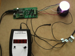
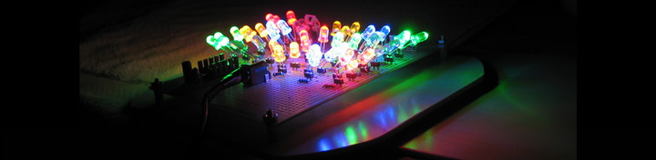
The Temperature Monitor in operation. One sensor is laying on the test bench and reports the ambient temperature. The other sensors are contacting various heat generating devices on the LED driver and LED heatsink. It is best to tack dwn the sensors with a little heatsink grease to get the best thermal connection.
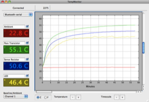
The logging program displaying the data collected monitoring the LED driver system.
The application was written in Real Software's object oriented Real Studio (now xojo) development system and binaries created for OS X (x86 + PPC), Windows 32 and Linux x86. Although the professional version I use is not cheap, the tool allows easy cross-platform application development. There is a less expensive personal edition that should compile this code (as well as a 30 day free trial).
Download Source (App + Arduino)
Go here for more information about the application and to download precompiled binaries.