
Remote Controlled LED Blinky

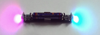
A client wanted to make a version of a blinky he sold to dancers and acrobats that could be configured wirelessly via a remote control. Using two high-brightness RGB LEDs it can display various built-in patterns and effects or can be programmed with custom patterns running at various rates via the remote control.
Both development and production costs were an issue so I choose an existing set of remote control plastics from a Chinese manufacturer and designed the LED controller to fit my client's existing enclosure.
Both development and production costs were an issue so I choose an existing set of remote control plastics from a Chinese manufacturer and designed the LED controller to fit my client's existing enclosure.
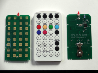
32-button 2.4 GHz RF remote powered by 3V coin cell. Ultra-low sleep current with the micro-controller woken by a key press. C code firmware. Bi-directional protocol allowed an external device to interrogate/configure the remote for special functions. Remote normally sent basic key press commands to the LED controller but also provided a special "link" mode to set common RF operating parameters in both the remote and LED controller so multiple pairs could operate in the same space. The plastic enclosure was designed for IR remote functionality originally. We put a red LED in the emitter location that blinked for button presses and other special functions for feedback to the user.
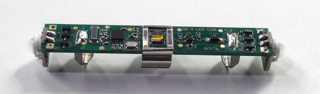
Battery powered 2.4 GHz RF LED controller. 3V regulator, two 3-channel HB LED drivers, combo RF transceiver/micro-controller, supporting circuitry and chip antenna fit on a 75 x 12 mm PCB. 0402 sized discrete components. The C code firmware implemented a full set of built-in functions as well as the ability to store several user-defined patterns EEPROM. In order to conserve power but remain responsive to ON button presses on the remote, the firmware slept the system, waking every two seconds to see if there was a power on command to receive. The remote would send the command for three seconds when the ON/OFF button was pressed.
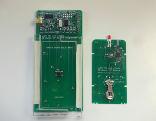
Manufacturing programming fixture for the remote. Assembled remote control PCBs are pressed into the fixture, making contact with pogo pins for programming and automatically triggering a programming cycle when inserted.
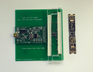
Manufacturing programming fixture for the LED controller. The final programmers had a 3D printed mount.