
High Brightness LED dimmer
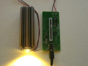
I built a prototype dimmer as part of an investigation into high brightness LED drivers. The driver is based on the Maxim 16820 step-down constant current converter. It supplies a constant 350, 700 or 1000 mA to one or more LEDs wired in series. With a 2 MHz switching frequency and inexpensive support circuitry, I had high hopes this part could support a high-frequency LED modulation algorithm. The prototype worked perfectly. Unfortunately the Maxim part is susceptible to ESD and goes into a very catastrophic latch-up condition (e.g. burns a hole through the PCB). I abandoned the Maxim part for use in a product but decided to share this circuit with LED enthusiasts. Please feel free to take the gerber, schematics, BOM and demo code for your own personal use. Download a zip file here.
I have 11 extra, unpopulated PCBs that I'm willing to give to good homes. Drop me a line to work out shipping. I use Accutrace to build my prototype boards. Very high quality. They have a great $10/each 10 board deal ($5/board for additional boards) and other promotions. I recommend them if you'd like to build your own set of these boards.
I have 11 extra, unpopulated PCBs that I'm willing to give to good homes. Drop me a line to work out shipping. I use Accutrace to build my prototype boards. Very high quality. They have a great $10/each 10 board deal ($5/board for additional boards) and other promotions. I recommend them if you'd like to build your own set of these boards.
Note: Be sure to connect the power supply before plugging it into AC to avoid frying the Maxim part. Try to avoid exposing the circuit to ESD. The circuit seems very reliable by following these two rules.
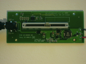
LED modulation is done using a PIC 12F615. The demo code implements a simple PWM modulator running at about 486 Hz. There is no perceived brightness linearization of the output.
Power is supplied with an external DC power supply, typically 12- or 24-VDC (28 VDC maximum). The circuit is a step-down driver so the input voltage must be higher than the maximum LED string Vf.
I also hacked a board to support a 12 VDC constant voltage LED array (no Maxim part or inductor). This board uses the N-channel MOSFET as a low-side switch connecting the array cathode to ground (the anode side is connected to Vin). I had to add a 78L05 5VDC linear regulator to provide +5 volts to the PIC (the Maxim part has a 5 volt output used by the original circuit). I used two of the ceramic capacitors on the PCB for the regulator compensation. This circuit is easily deduced from the high resolution versions of the following images in the slideshow.
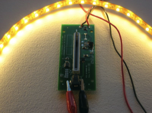
Driving a flexible LED array
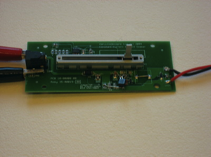
Hacked driver (you can see the regulator)