
Battery Buddy 1
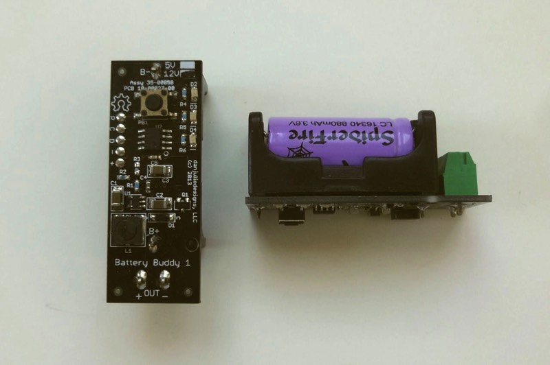
Battery Buddy 1 is an attempt to productize this hack as an Open Source Hardware design. It has two configurations providing either 5VDC or 12VDC outputs. I built a set of prototypes and found lackluster interest with the group of people I showed them too so I decided to move on to other projects and just post the design files here for anyone who might want a small power supply that has an easily replaceable battery.
I have found these devices useful to power devices I am debugging, for costumes and for powering things in the field.
I have found these devices useful to power devices I am debugging, for costumes and for powering things in the field.
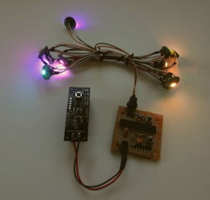
Powering a 12V LED array
Features
- Power on/off Control
- 5-level Battery Voltage Display on Red/Yellow/Green LEDs
- Low-battery indication
- Low-battery shut-down
- Uses replaceable, rechargeable Li-ion batteries
Specifications
- Auto-shutoff Battery Voltage: ~3V
- Low Battery Indication: ~3.2V
- 5VDC Version Max Current: ~1 A
- 12VDC Version Max Current: ~500 mA
- Quiescent Current (sleeping): ~30 uA
- No-load Current (on): ~10 mA
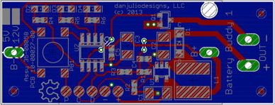
Downloads
bb1_design_files.zipThe download file includes
- Gerbers for the PCB
- Eagle CAD (5.X) source files
- Schematic PDF
- BOM for both 5V and 12V versions
- PIC source code and HEX file (for MPIDE)
- IC Specifications
Operation
- Press and hold the button for 3 seconds to turn on or off. The LEDs sequence Red->Yellow->Green when turning on and Green->Yellow->Red when turning off.
- Press and release the button quickly to display the battery level. Five battery levels are displayed on the LEDs for 500 mSec : Green; Green-Yellow; Yellow; Yellow-Red; Red
- The Red LED blinks slowly when low-battery condition is detected (below 3.2V)
- Power is turned off and the device sleeps when the battery voltage reaches about 3V
Notes
- The firmware supports fault detection (pin 7) and will shut down the power supply when pin 7 goes low. Unfortunately the circuit (resistor R3) didn't work correctly and this feature is disabled. Do not load resistor R3 on the PCB. A future version might have a current sense resistor and comparator (ideally, in the micro).
- There is no reverse-battery protection. I would add a MOSFET reverse battery protection circuit if I spun the board but for not make sure now to reverse the battery. Things might get very hot!
- The code is written for Microchip's MPASM assembler. ICSP signals are brought to the side of the PCB for use with a programmer such as the PicKit 3 or ICD 2/3.
- The board will work with either Texas Instrument's LMR62421 or Linear Technologies LT1935 IC. Part and voltage specific components are listed on the schematic.
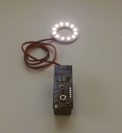
Powering a 5VDC LED display
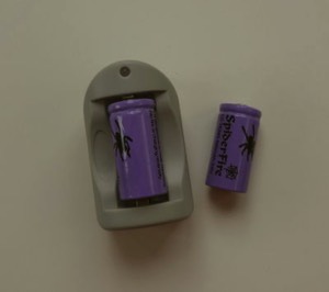
Batteries and Charger
Look for 3.6V 16340-style rechargeable Li-Ion batteries. I bought mine from DealExtreme. Make sure that they are 3.6V (not 3V).