Various Hardware Tools
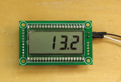
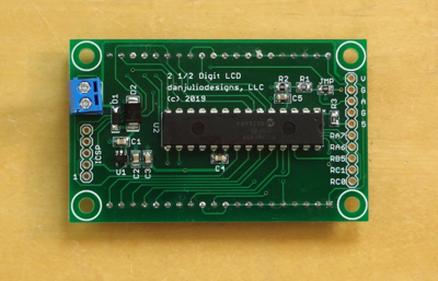
I developed these tools as part of the development of some other project.2 1/2 Digit LCD DVM
This project has been useful in monitoring the 12V batteries used in the MPPT Solar Charger project, however it came about more-or-less by accident. I bought some 4-digit LCD displays from eBay without researching them and found out they were not multiplexed (they need a driver output for every segment). I was planning to use them with a tube of old PIC16F913's I had laying around from the HRMI days but it doesn't have enough pins to drive all 4 digits. So I bailed on the extra digits and just made a quick-and-dirty 2 1/2 digit (2 7-segment digits for units and tenths, and a 2-segment digit for tens to display a '1' or nothing). Design here and shared Mouser BOM if you want to see how easy it is to drive an LCD. It's pretty jenky for a DVM with only 5-15V range but it serves my purpose. Requires about 1 mA.
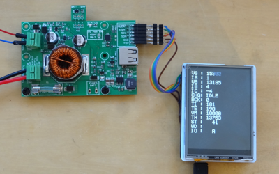
MPPT Solar Charger Monitor
Just a Linksprite LCD shield stuck on top of an Arduino Leonardo, but it allowed access to the MPPT Solar Charger during development. The LCD readout was helpful but it also has a serial command interface that can dump data quickly which was very helpful while debugging various algorithms. No schematic but the necessary connections are documented in the code if you want to add one to your charger.
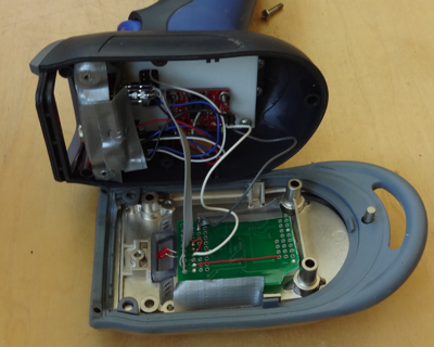
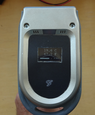
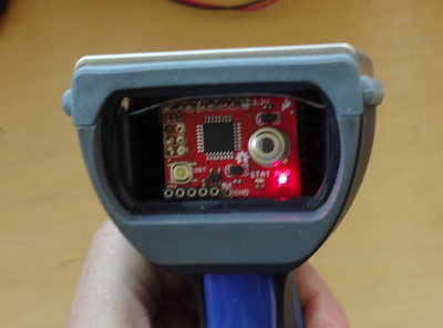
IR Temperature Monitor
An IR temperature monitor based around the Sparkfun MLX90614 Eval Board, along with a 128x96 pixel SSD1306-based OLED display from some TI dev kit and a Sparkfun LiPo charger board in an old wireless barcode scanner enclosure (I re-used the built-in 3.7V LiPo battery and push-button).
Unfortunately I never drew a schematic but the code is here if you are interested.
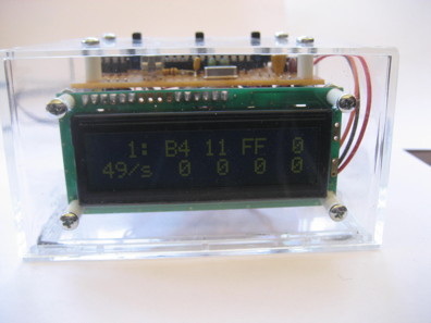
DMX Readout
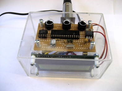
One component of my lighting system design utilizes DMX as a communication protocol between my controllers and commercial LED fixtures. The system has the ability to map various data fields to any DMX channel. This is fairly easy to test with RGB fixtures but becomes difficult with more complex fixtures. I found Max Pierson’s excellent Arduino DMX receiver code. I hacked on it a bit to add a standard parallel LCD display that can display any eight sequential DMX channels in real time. The display also shows the number of frames being transmitted per second. The whole thing was wired on a perf-board and thrown into a cheap plastic case that originally held a Christmas ornament (a mistake, these cases are too fragile).
Circuit Diagrams (Arduino-based and Stand-alone ATMega168) and Arduino Code. Note that this updated version compiles under Arduino 0021. I had only three signals left over for control after connecting the serial interface and LCD. I implemented a three button solution for setting the starting address. Up and Down buttons increment or decrement the starting address by 1 for each press. Holding the Fast button causes the channels to change rapidly while Up or Down are held. Holding Up and Down together resets the starting channel to 1.
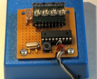
Power Supply Voltage Display
I bought an inexpensive adjustable power supply based on the 732 regulator IC from canakit and then designed a simple digital voltage readout for it using a PIC 16F373A and 2.5 volt reference. I scrounged around and found some 0.1% resistors that summed to 28.005 k-ohms to go with a 4.000 k-ohm 0.02% resistor I had to create the input voltage divider (0-20 volts scaled down to 0-2.5 volts). The displays were bright enough that I didn't need common cathode drive transistors and could sink the current for an entire digit with on PIC IO pin. Probably took 3 hours in total. Obviously it would have been a better use of my time to have just purchased a cheap DPM on ebay but we don't always choose the most efficient route and I didn't want to wait. If you're in a bind but have a few parts laying around perhaps the circuit and program in this zip file can help you out. You can easily adjust the input voltage divider or code to deal with whatever resistors you have at your disposal. Write it in C for your favorite microcontroller or an Arduino and the coding will only take a few minutes.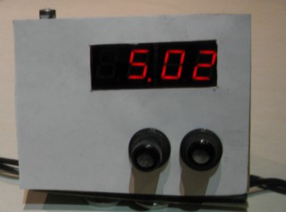
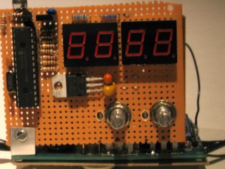
Event Counter
Along the same lines as the power supply voltage display I also built an event counter using a PIC 16F84A and Siemens DL2416T display. I have primarily used this event counter to count the number of packet failures I see in the digital radio that is part of the lighting control system. However it has proved helpful occasionally for other projects as well. It can count to 19999 and then indicate an overflow. The "1" is indicated by the LED turning green. An overflow is indicated by the LED turning from green to red. Another very quick and dirty project based on an immediate need. I had the display and PIC. I only used this alphanumeric display to display numbers 0 - 9 so I could tie off unused data inputs and have the PIC only output BCD information. Schematic and code if you're interested.